top of page
CURLICUE
An unrestrained wired future.
PROJECT TYPE
Academic
Course: New Product Development
Type: Individual Project
PROJECT TYPE
Academic
Course: New Product Development
Type: Individual Project
MY ROLE
Ideation, Concept Scoring, Prototyping, Product Costing,
Poster Design
DURATION
Five Months
January 2018- May 2018
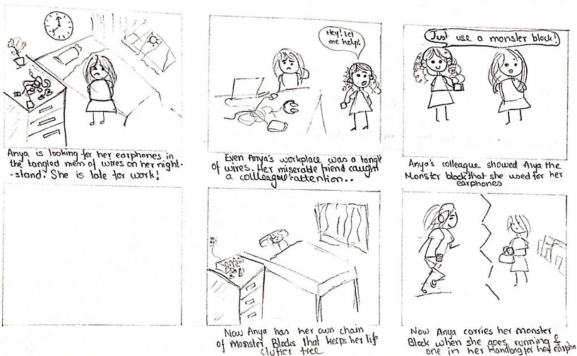
Need Identification
We couldn't find a single existing product in the market that automatically detangled earphone wires or a dock that could handle the hundreds of cables cluttering our workspaces, one that was easily detachable and was suited for mobility
A google survey of 120 college students and young working professionals showed us we weren't the only ones.
And we were all excited for a solution.
We wanted to make a product that
Would take care of your wires everywhere.
On jogs? Yep.
At work? Definitely
One wire?Of course.
Twenty? Why not?
A quick assessment of what our target market showed that
They really valued the aesthetics of the product. Handling, weight and modularity also seemed very important to most individuals.
Benchmarking
Need Metric Matrix
Importance rating


on
Brainstorming
we generated 4 concepts
1. Simple Winding

3. Magnetic Silicone

2. Circular spring
4. DC Motor Reel In
on
Concept Screening
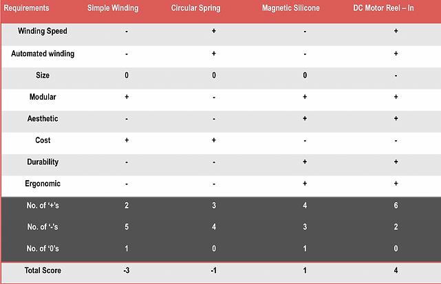
Each concept was checked to see if they could solve unique customer requirements.
They were given a qualitative score of:
-1= Will not be satisfactory
0= Doesn't affect
1= Will satisfy
The DC Reel In concept was a clear winner.
to satisfy the left brained ones in class, our professors asked us to also
Concept Scoring
Each customer need was given a weightage to determine how important it was that our product addressed/met the need. This was based off of the initial survey we had conducted.
Then for each need we rated how well the concept satisfied a particular need. The scale was expanded (from -1, 0,1) to 1 to 5 where
1= Will not satisfactory at all and,
5= Will satisfy completely.
Multiplying these ratings with the weight of the customer need it referred to gave us a much better utility analysis of the concepts.

The DC Reel-in concept won again!
It was clear, we were going ahead with the DC Reel In concept.
It was time to build a
Prototype
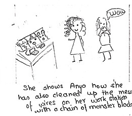
Story Board
Concept Sketch
The idea was to have modular blocks, one for each cable, with magnetic walls that can attach to form a long chain of blocks for all your cables.
The left face of the block and a thin strip of the front(the trace in the sketch) and backtogether, form a door that can be removed to to allow a user to thread in his cable , into the mouth, one loop over the housing and out at the back
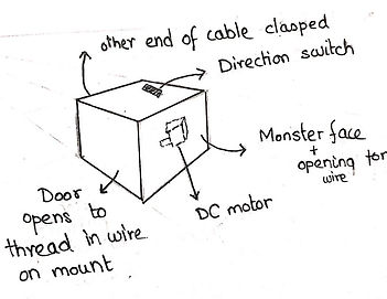
The design was a monster block.
That is, one side would be a little monster and the monster's mouth would be the output side or the usable side of the cable
Inside the block would be a DC motor with its axle mounted with a plastic housing, to reel in the wire
How it will work:

The plugs are clasped at the back of the box


Individual monster blocks have magnets on their walls and can form a chain of monster blocks.

This helps organise as many wires as one needs and also makes wire organising very aesthetic.
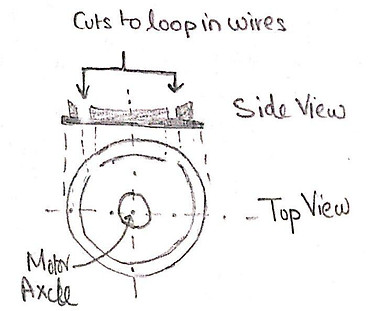
1. To start with, the user slides in the wire through the side door and loops it around the circular plastic housing mounted on the axle as shown from Step 1 to 4 (flow of the blue wire)
2. A switch at the top of the housing turns the axle of the DC motor anticlockwise (see red arrow)

3. The switch can be turned the other way to unload the wire.
4. The wire can be removed from the block through the same side door
With a clear idea of the model, we started building the prototype.
from left to right the
Electronic Components
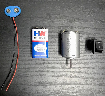
Battery Clip Connector
9V Battery
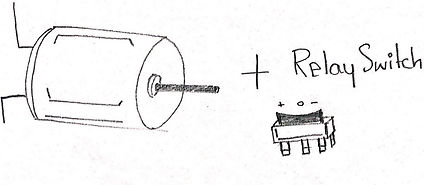
Mini DC Motor
Bi-Directional Switch

Relay switch connections
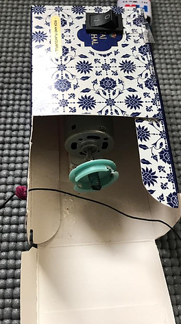
Other Components
from top left, anticlockwise

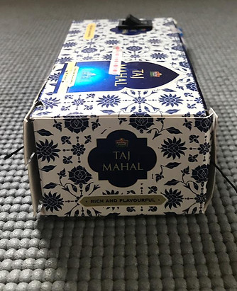
A box of tea bags that would substitute as the outer case of the reel in box
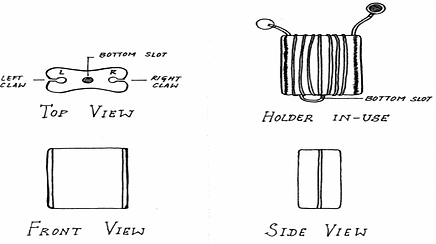
A plastic reel we found by breaking open an ID card holder that interestingly used the second concept we has been considering.
The best thing about it was that it already had one of the two slots we required, made.
A simple coin magnet from Amazon that we used to keep the DC Motor from rolling away and act as a stand.
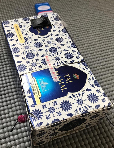
Final Prototype


A single Monster Block
Top Latch to open side door
Side door
Power Source
(Will be housed inside)
Front with Monster Face
Back Wall with Clamp and wire channel

Open
Shut

Relay Switch
Plastic Housing on DC motor's Axle
Problems and Learnings
For a while the wire was getting wound around the axle on the motor. We realised we should not only have a shorter axle but also hold both ends of the wire in tension. This is when we introduced a second clasp, on the front wall hole.
The diameter of the plastic mounting was bigger than the DC Motor axle so we used pieces of eraser and some glue to make sure the mounting stayed on the motor motor axle
We also had to cut out another opening in the plastic mounting and we suggest maybe 3D printing the plastic mount to prevent bloody fingers.
We advice using a battery with a lower voltage or a motor with a 300 rpm or lesser to prevent parts from flying away and risking injurious to innocent on lookers or if you simply want to avoid using a PWM/ any other speed controller.
Note: We did not include the GPS GSM module for this first prototype.
with a high fidelity prototype, we went ahead with
Concept Testing
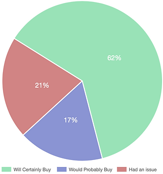
Purpose: To asses acceptability of the product, watch user-product interactions to identity improvement opportunities and to hear changes consumers would like in the product
Survey Population: 25 University Students and 4 Working Professionals
Communication of concept: Physical Prototype and CAD model
Results :
Concerns that we evaluated and proposed as improvements on this concept
post testing with a sample population we decided on
Product Costing
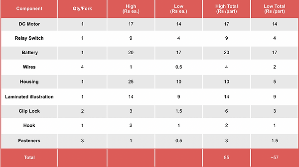
Other Costs:
Manufacturing costs
Cost of assembly
Cost for supporting production.
Equipment Cost
Marketing and Distribution cost
Also, to consider the impact of DFM (design for manufacturing) decisions on other factors.
Considering a 20% margin and a rough estimation of the above costs assuming 200 pieces produced a month, for product was priced at:
Rs. 199
~Fin~
bottom of page