Improving The Design And Manufacturing Of Wings For a FSAE Race Car
PROJECT TYPE
Academic: Technical Solutions for Real World Problems (TARP); Group Project
CONTRIBUTION
Research, Conceptualisation and Solidworks model, Manufacturing
DURATION
6 months
Goal for Wing Design
Achieving greater downforce and higher downforce-drag ratio through optimisation of wing configuration along with use of a footplate and side fin in the endplates to reduce pitch sensitivity and reduce the tire drag.
Goal for Manufacturing
-
Lighter wings
-
Minimize manufacturing error
-
Maximaze dimensional accuracy
-
Achieve better Mounting for better stiffness and reliability.
Design Phase


First, to optimise the wing configuration, i.e. the flap positions, the angle, 2D simulations were carried out. This helped us decide the final wing elements configurations
The next goal was to achieve greater downforce and higher downforce-drag ratio through optimisation of wing configuration along with use of a footplate and side fin in the endplates to reduce pitch sensitivity and reduce the tire drag.
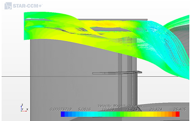
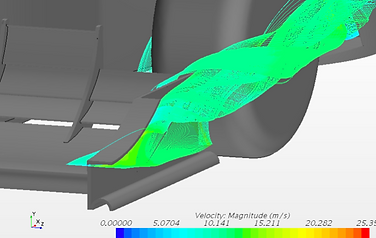
My teammate used streamlines to demonstrate the vortices generated by incorporating a footplate in the design interact with the vortices of the sides fin and they energise each other , reduce the air around the tire and reduce drag.

The above is a table of different footplate and Side-fin design iterations we carried out to conclude that a footplate with a 36 mm inner diameter gave the highest downforce and lowest drag for both the wing and time tire.


To validate the design of the CAD model, simulations were carried out on ANSYS to check for the structural integrity of the wing.
Manufacturing
Based on a Material Selection Matrix, on the basis of several properties such as – Surface finish, Weight, Stiffness , we chose Carbon Fibre as our material and Epoxy and Hardener as the respective Matrix – Reinforcement system
Also, to get the right mix of releasing agent to get the easiest de-molding we iterations and decided on Wax + Henkel.


‘Wet Layup’ was the chosen manufacturing technique because:
1. It can be controlled easily.
2. Good surface finish.
3. Very manual in nature.
Parameters decided:
Vacuum Pressure = 600mm Hg
Weight of resin = 450g
Time for Layup = 15 minutes
Wing Layup using wet layup technique

Final Prototype
Incorporation of spar to give structural rigidity
Use of footplate to improve downforce and reduce pitch sensitivity

A half Step Wing for Visual verification of improved manufacturing
Incorporation of PU foam on ribs for increasing surface area of bonding
Use of side fin for improving flow around wing and tire