Sidestand Design Change for an Electric Vehicle
Final Year Project's Design Aspect
Note: The designs have been altered for project submission since the original designs belong to the OEM they were designed for.
PROJECT TYPE
Professional,
Team of 3
CONTRIBUTION
CAD Design, Concept generation, FMEA, Interviews, Analysis and ECR Process Verification
DURATION
3 months
March'18- May 2018
Objective:
1. Re-design and test an electric scooter's sidestand.
2. Observe the performance of a newly designed bug handling process by taking the bug on the side stand through the entire BUG-ECR-ECN process.
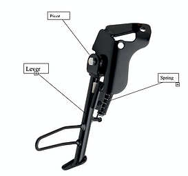
Problem definition: Sidestand Design
The initial side stand was a lever setup with a spring attached at a point on the lever and anchored on the chassis at an offset from the side stand pivot point. Though the setup was easy, it did not give enough flexibility for aesthetic integration into the design language of the company.
A bug was raised on the existing design which called for a design change.
Need Definition
-
It needs to be a mechanism which allows for flushness with the body panels in the retracted position which serves the purpose of protecting the internal parts from the elements as well as has aesthetic appeal of undisrupted lines.
-
It also has to be light enough to fall within the overall weight requirement of the scooter.
Design
Based on the requirements, the team realised a four bar mechanism (assisted with a spring and a magnet) might just be the simple solution to all the problems.
First Concept Design
We decided on part dimensions from existing CAD models. I used Solidworks to design the four links.
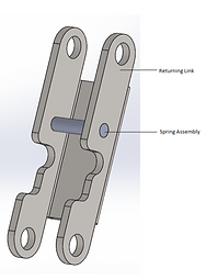
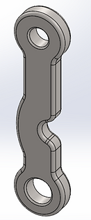

Base Link
Control Link
Returning Link
Main Link

After some minor modifications we assembled the 4 parts on Solidworks and did FMEA before making a test setup of the assembly:

But when we tested it for fatigue failure for 40000 cycles,it failed after 5563 cycles.
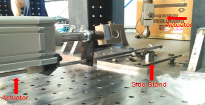
Assembly of Concept 1

Test ruled out due to frequent breakage of bolts
We realised the following bugs needed fixing:
-The sidestand required a sensor to cut off the motor when deployed.
-There was metal interlocking and noise generation in this design and,
-It failed a 40000 cycle fatigue test due to bolt breakage.
Second Concept Design
We carried out a RCA on the three bugs above and did a new FMEA.
For the sensor, a threaded hole of 6mm diameter was drilled on the front link of the side stand to accommodate the magnet.

To accommodate the sensor, a threaded hole of 6mm diameter was drilled on the front link of the side stand to accommodate the magnet.

Similarly, the base link and rear links were machined by 1 mm to reduce noise.
Second Concept Design Verification
CAE Team carried out displacement and stress distribution tests using linear analysis.


Bolts were case hardened for durability (hardness increased from 10 HRC to 15 HRC)

The new concept was now tested for 30,000 cycles and it Passed!


Tracking Design Progress
